Lab 4 - Motors and Open Loop Control
The goal of Lab 4 was to solder our motor drivers to the Artemis and connect them to the car, allowing for the car to be controlled by the Artemis with open loop control.
Prelab:
Circuit diagram:
The circuit I decided to use for wiring the motors is as diagrammed below:
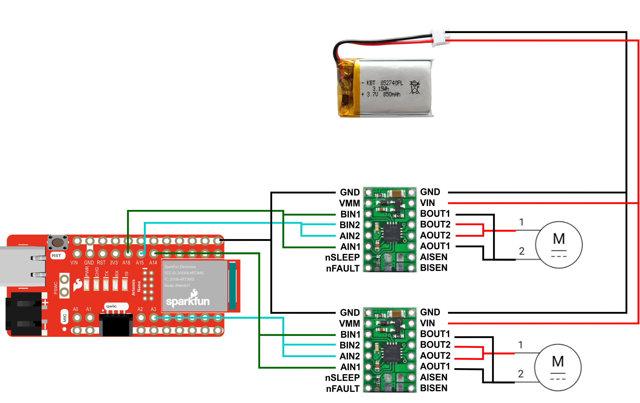
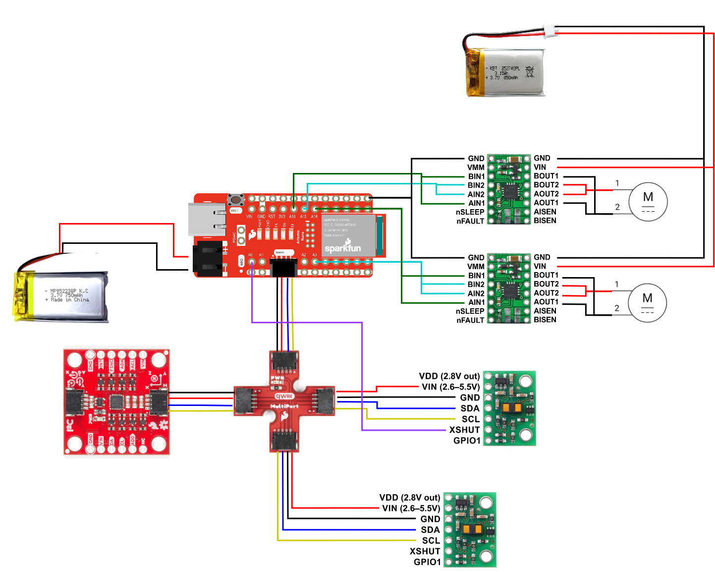
In order to be able to drive the motors, the GPIO pins had to be PWM capable, which meant pins 8 and 10 couldn't be used. Additionally, they had to be analog pins. I ultimately used pins A3, A14, A15, and A16 as they were located on the opposite side of the Artemis programming port, meaning the programming port could be at the edge of the car while the pins would be closer to the motors. The full circuit with IMU and TOF sensors is below:
Battery:
The Artemis and the motors are run off of separate batteries, with the Artemis being run off of a 650 mAh battery and the motors running from a 850 mAh battery. This has the advantage of avoiding transients, or sudden changes in voltage or current. For example, if everything was connected to one battery and the motors suddenly drew a lot of current, the battery voltage could temporarily drop outside of the Artemis's operational voltage range, shutting it down. Separating the batteries avoids these types of events.
Lab:
Verification of Motor Drivers
I first soldered the motor driver to the Artemis and tested it could output PWM signals. To test the motor driver, I connected an oscilloscope to the output signal of the motor driver and grounded it. I powered the driver from an external power supply at 3.7 volts, as that is the voltage that the 850 mAh battery will provide. A video showing the setup and the resulting 50 percent duty cycle pwm waves for both drivers is shown below:
Wiring to Car
Next, both motor controllers were wired into the car. This involved removing the preexisting circuit board and soldering those motor connections to the motor driver output. To test these motors, I kept the drivers attached to the external power supply and made the following code in the loop funtion to drive them forwards for 5 seconds, and backwards for 5 seconds:
                    analogWrite(3, 150);
                    analogWrite(16, 150);
                    analogWrite(14, 0);
                    analogWrite(15, 0);
                    delay(5000);
                    analogWrite(14, 150);
                    analogWrite(15, 150);
                    analogWrite(3, 0);
                    analogWrite(16, 0);
                    delay(5000);
The following video demonstrates this code running on the car:
Next, I tested running everything fully from battery. This involved soldering the battery cables to the motor driver. Then, the above code was run with only these batteries as power.
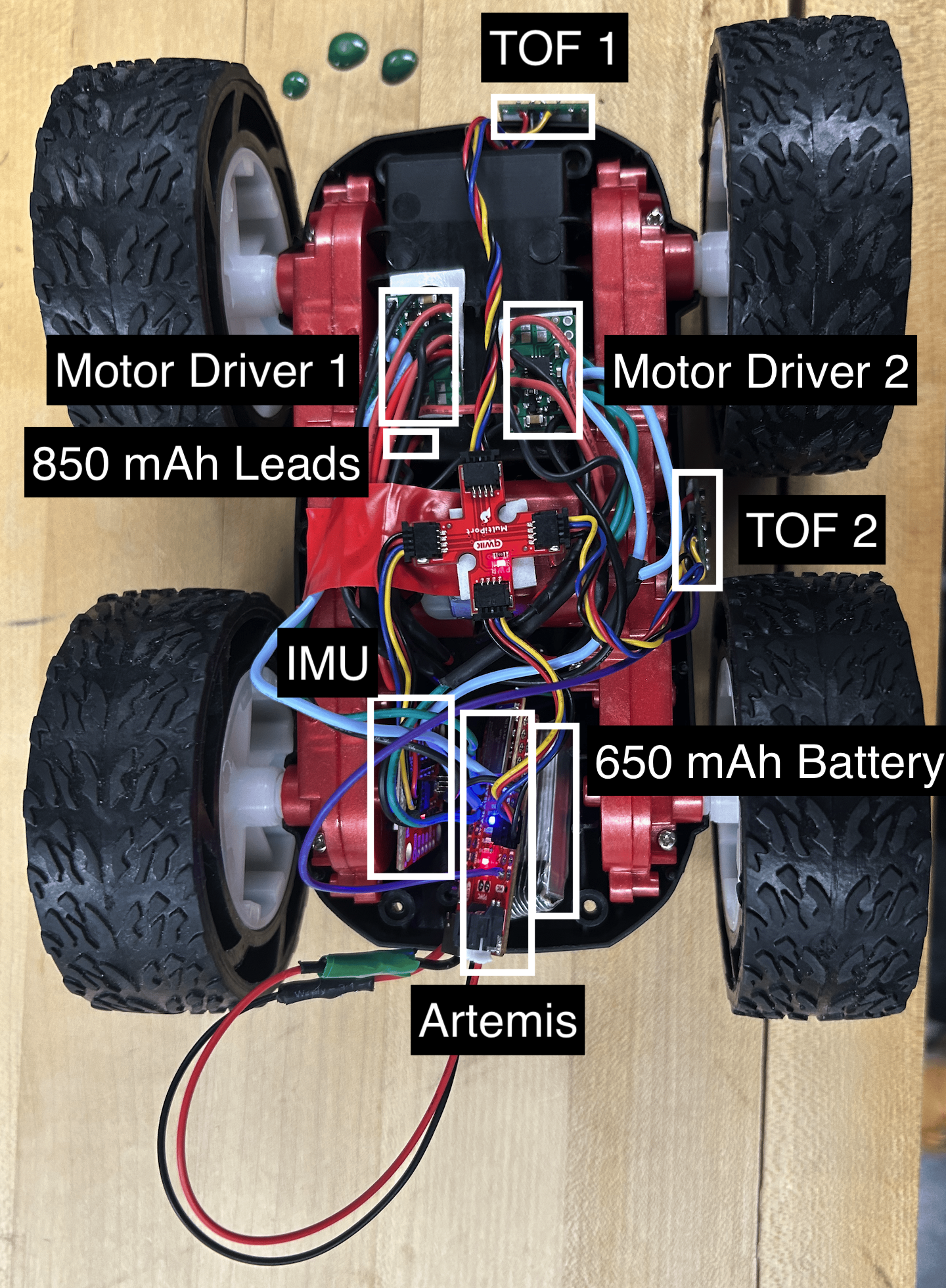
I then affixed each component into the car with foam tape. I placed the motor drivers by the cable for the 850 mAh battery and away from the Artemis and IMU to avoid EMF interference. I had the QWIIC multiport in the center so each component could be easily reached, and put the TOF sensors on the outside to detect obstaces..
PWM Limits
I then tested what PWM values the motors would actually operate under, by changing the values provided in AnalogWrite out of 255. Firstly, I found that an analog write value of 50 for both motors was sufficient to make the car go forward under load. Without load, this only drives one motor, implying that with load one motor was spinning the other wheels enough to overcome static friction. An analog write of 60, or 23.5% duty cycle would drive both forward without load. For going backwards, this went up to 70.
To have the car spin on axis, I found that a write of 140 was necessary to get both wheels running, although it took a bit for the left wheels to start moving. 150 ensured that the car would immediately turn. The following video shows an on axis turn with write values of 140.
Calibrating motors
I found that my right wheels spun faster than my left wheels, and rotating them by hand, I could feel that the left wheels had more resistance. Running both wheels at 100 caused the car to veer left.
To fix this, I used a multiplication factor to increase the pwm written to the left wheels. I found at low speeds a value of 1.52 worked the best, although at higher speeds a value of 1.4 was sufficient. The following code shows the adjustment variable I played with, and the car going in a straight line.
                    analogWrite(sig1, 140);
                    analogWrite(sig3, 140*adjust);
                    analogWrite(sig2, 0);
                    analogWrite(sig4, 0);
I experimented with adding a flat value instead of multiplying, and found 40 worked alright, but overall the multiplicative scaling was more consistent. I also found that setting both motors to 0 to stop it would result in the car pivoting left. I counteracted this by running the right motors in reverse for a short period when stopping.
                    //stopping
                    analogWrite(sig2, 50);
                    analogWrite(sig4, 0);
                    analogWrite(sig1, 0);
                    analogWrite(sig3, 0);
                    delay(50);
                    val = 0;
                    analogWrite(sig2, 0);
                    analogWrite(sig4, 0);
                    analogWrite(sig1, 0);
                    analogWrite(sig3, 0);
Open Loop Control
To demonstrate open loop control, I programmed the car to drive in approximately a square, using the following code:
                    //deadband
                    analogWrite(sig1, 70);
                    analogWrite(sig4, 70*adjust);
                    analogWrite(sig2, 0);
                    analogWrite(sig3, 0);
                    delay(50);
                    //normal speed
                    analogWrite(sig1, 40);
                    analogWrite(sig4, 40*adjust);
                    analogWrite(sig2, 0);
                    analogWrite(sig3, 0);

                    delay(2000);
                    //turn
                    analogWrite(sig1, 140);
                    analogWrite(sig3, 140*adjust);
                    analogWrite(sig2, 0);
                    analogWrite(sig4, 0);

                    delay(250);
This would loop to go straight slowly, then turn. A video of this behavior is below:
5000 Tasks:
I found the frequency of analogWrite by writing 50% pwm to pin A2 and measuring it with an oscilloscope.
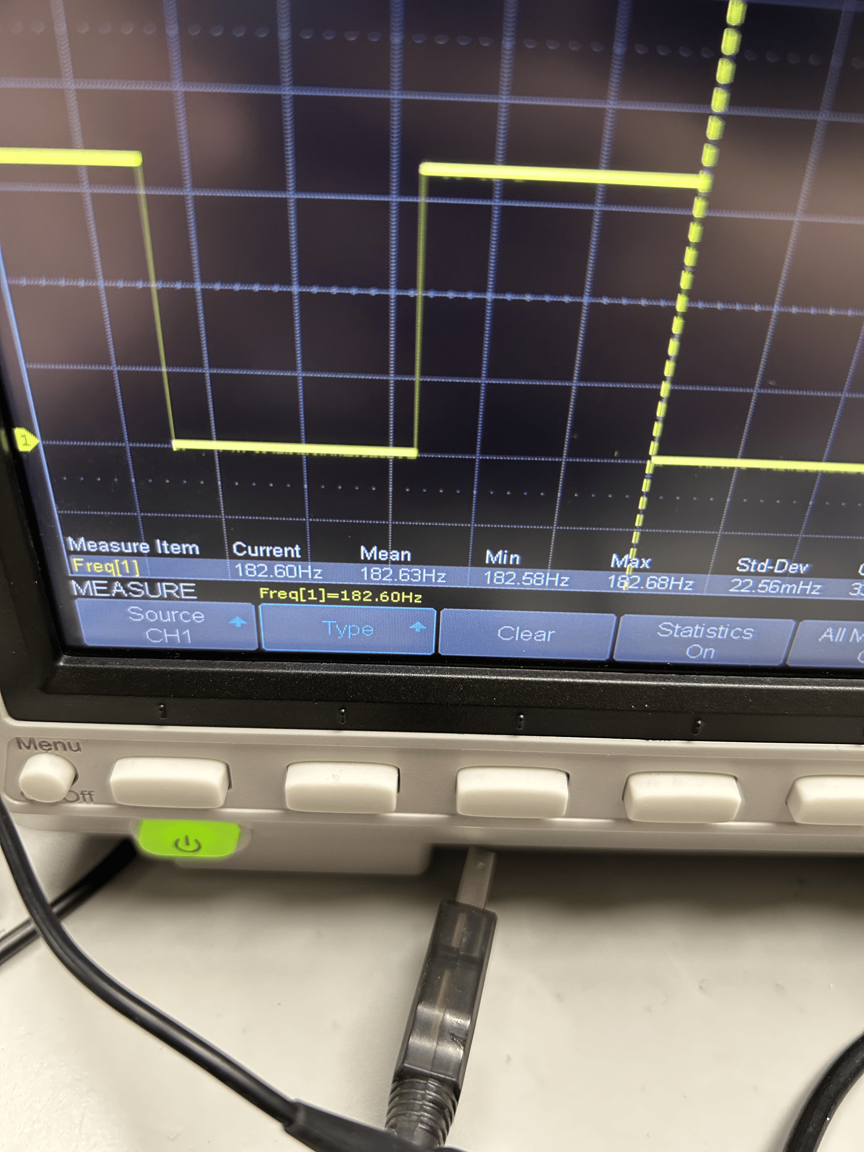
This found the frequency to be about 182 Hertz. This is a relatively low frequency for PWM, but appears to be sufficient for these motors as it gets them running at a relatively consistent speed. The concern of low frequency PWM is that the motors would be less smooth, as the motor acts as a lowpass filter and ideally only recieves a dc average voltage, but with low frequencies may also be influenced by the AC component. Using timers to produce a faster PWM frequency could hypothetically make the motors run smoother and less noisely.
To test the lower limits of the PWM once static friction had initially been overcome, I set the motors to run at the minimum values I found above and then dropped them until the wheels no longer moved. This can be seen in the start of the open loop code above. I found that I could keep moving straight forward dropping to an analog value of 40, or a duty cycle of 15%. For spinning on axis, I could drop from 140 to 110 analog and keep spinning, or a duty cycle of 43%. Below is a video of the spinning at a lower PWM:
I initially did this testing by running the starting value for 50 ms. I found through experimentation it needed to be ran for at least 20ms, as otherwise the wheels would take longer to spin up, shown below with 15 ms:
References
When soldering and completing code for this lab, I discussed concepts and potential layouts with Giorgi Berndt and Jorge Corpa Chunga. I additionally referred to Mikayla Lahr's webpage from last year as reference for how to layout my webpage.